Essential information about preseason prep for your Parker Grain Cart.
Checks before initial use:
Lubricate all grease fittings.
Ensure that PTO is in good operational condition. Make sure that this telescopes in and out as it should and is greased properly.
Change auger gearbox oil yearly using 80W-90. Check the oil level with the vertical auger titled all the way down.
Verify drive belts or chains on double auger carts are properly tensioned and in good condition. The tensioner springs should measure 1 ¾” when belts are tensioned. The tensioner springs for the vertical auger should measure 3” and the horizontal auger should measure 2 ¾" when the chains are tensioned.
Verify transport lights are working properly.
Checks after initial use:
Verify track alignment.
Verify tire pressure.
Verify torque on wheel bolts or track idlers.
SETUP & REFERENCE GUIDE
Parker Cart Service Points:
Lubricate all grease fittings.
Ensure that PTO is in good operational condition. Make sure that this telescopes in and out as it should and is greased properly.
Change auger gearbox oil yearly using 80W-90. Check the oil level with the vertical auger tilted all the way down.
Verify transport lights are working properly.
Verify drive belts or chains on double auger carts are properly tensioned and in good condition. The tensioner springs should measure 1 ¾” when belts are tensioned. The tensioner springs for the vertical auger should measure 3” and the horizontal auger should measure 2 ¾" when the chains are tensioned.
Flighting - Check flighting to make sure that this is not worn past an acceptable amount and is in good condition.
Safety Components - Ensure safety chains, lights and SMV's are all in good working condition.
Hopper Components - Ensure interior of cart is in good working condition with no loose components inside.
Tarp - Ensure Tarp is free from tears and rolls freely.
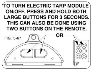
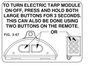
If equipped with electric tarp, please refer back to decal for specific instructions.
Undercarriage
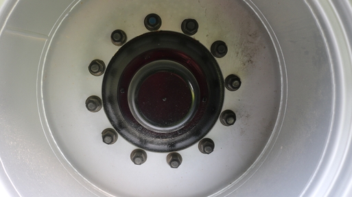
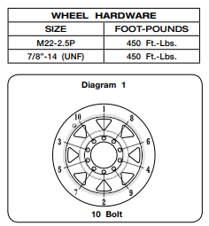
Wheels: Ensure that wheels nuts are torqued to the proper spec. On new carts especially it is critical to re-torque wheels to the appropriate spec once a load has been applied to the cart.
Tires: Ensure that tires are in good working condition. Ensure that tires are operating at the proper pressure recommended in owner’s manual.
Brakes: If a cart is equipped with brakes, ensure that brakes are not dragging and in good working condition. Make sure caliper and disk is in good shape. Make sure the tractor pulling this cart is equipped with the proper brake hook-up. Failure to connect brakes when operating may cause heat build-up and brakes to drag even though they are not connected due to oil expansion in lines.
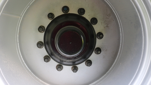
Wheel Nuts
Tracks:
Ensure track belt is in good working condition and free from rips and tears.
Ensure that belt is running true and is aligned properly. We do not want any heat building up from improper alignment. After running the cart for ½ mile to mile in straight course, check guide lugs for heat build-up on both sides. If heat is present make adjustments. Refer to manual for proper steps.
Check belt tension. Current tracks are equipped with hydraulic tension. Ensure that hydraulic pressure is within 100 PSI of recommended pressure.
Bearing and Idler Condition. Ensure wheel nuts and lugs are torqued properly. Check bearings for end play. This can be done by jacking up the track and taking the tension off.
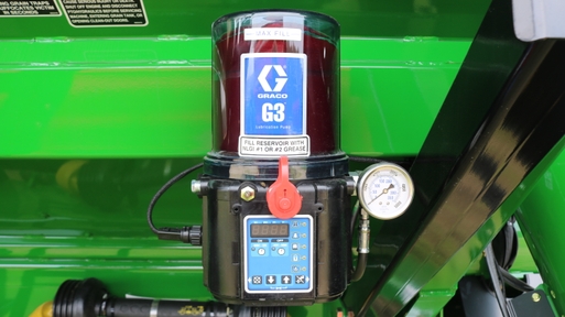
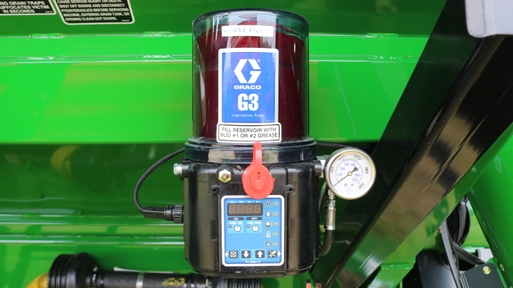
Lubrication: Ensure that autogreaser is set at the proper interval and full of grease. If cart is not equipped with autogreaser, ensure that grease bank lines are full and in good working condition. Grease hubs on wheels. All grease locations have purgeable seals.
Autogreaser
Scale Components:
Ensure proper calibration number is stored in scale device.
Ensure that all wires are routed properly and connected securely to junction block and load cells.
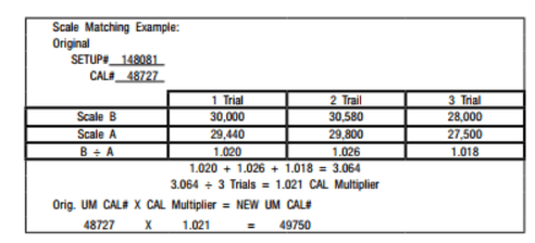
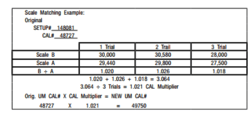
For Recalibration refer to the equation below. We need to make sure we are using full cart loads. In addition to this, it is recommended to use the sum of several cart loads as this will increase our accuracy with a larger sample size.
Operation Checks:
Ensure auger folds out and locks properly.
Condition the tracks if they are still tacky/green rubber.
Ensure PTO is operated at 1000 rpm actual speed (operating too slow can cause severe driveline damage).
Verify the tarp is open before unloading.
Ensure the joystick is connected to the same battery source as the 7-pin plug on the cart (if equipped).
Ensure all valves on the joystick hydraulic block are locked in the neutral position (if equipped).
Tractor Hookup:
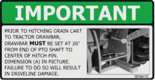
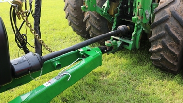
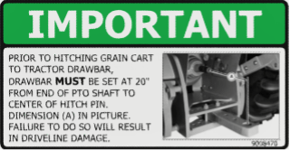
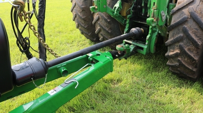
Ensure drawbar position is 20 inches from the PTO.
Verify the proper category hitch and pin are being used for your specific grain cart.
Install plastic wear shoe underneath the grain cart hitch to reduce wear.
Hook up safety chain.
Hook up SCV hoses in the desired order.
Set all hydraulic flows to 4-5 GPM on standard units.
Set hydraulic flow to 4-6 GPM for units equipped with a joystick.
If equipped with a water delivery system, set the hydraulic flow for the pump to a minimum and then increase the hydraulic flow until the water pressure reaches 40-60 PSI.
Essential information about preseason prep for your Brent Grain Cart.
Checks before initial field use:
Lubricate all grease fittings.
Change auger gearbox oil yearly using 80W-90. Check the oil level with the vertical auger tilted all the way down.
Ensure track auto-greaser is functioning properly if equipped.
Verify tracks are in alignment.
Verify torque on wheel bolts or track idlers.
Verify tire pressure.
Verify drive belts on double auger carts are properly tensioned and in good condition. The tensioner springs should measure 1 ¾” when belts are tensioned.
Verify transport lights are working properly.
Checks after initial field use:
Verify track alignment.
Verify tire pressure.
Verify torque on wheel bolts or track idlers.
SETUP & REFERENCE GUIDE
Brent Cart Service Points:
Ensure that PTO is in good operational condition. Make sure that this telescopes in and out as it should and is greased properly.
On double auger carts, check drive belts for wear. Make sure they are tensioned properly and oiled properly if applicable.
Check gearbox oil. Ensure that oil and box is in good condition along with being filled with the proper amount of oil.
Lubrication Points - Grease all applicable areas. Common areas of need: U-Joints/drive components, bearings, Fold pins and linkages.
Verify drive belts on double auger carts are properly tensioned and in good condition. The springs should measure 1 ¾" when belts are tensioned.
Flighting - Check flighting to make sure that this is not worn past an acceptable amount and is in good condition.
Engagement Components - Make sure that the drive dog connection between the upper and the lower is not worn and significant marring is not present.
Safety Components - Ensure safety chains, lights and SMV’s are all in good working condition.
Hopper Components - Ensure interior of cart is in good working condition with no loose components inside.
Tarp - Ensure tarp is free from tears and rolls freely.
If equipped with electric tarp, please refer back to decal for specific instructions.
Double Auger Grease Bank
Undercarriage:
Wheels: Ensure that wheel nuts are torqued to the proper spec. On new carts especially, it is critical to re-torque wheels to the appropriate spec once a load has been applied to the cart.
Tires: Ensure that tires are in good working condition. Ensure that tires are operating at the proper pressure recommended in the owner’s manual.
Brakes: If a cart is equipped with brakes, ensure that brakes are not dragging and are in good working condition. Make sure caliper and disk is in good shape. Make sure the tractor pulling this cart is equipped with the proper brake hook-up. Failure to connect brakes when operating may cause heat build-up and brakes to drag even though they are not connected due to oil expansion in lines.
Wheel Nuts
Tracks:
Ensure track belt is in good working condition and free from rips and tears.
Ensure that belt is running true and is aligned properly. We do not want any heat building up from improper alignment. After running the cart for ½ mile- 1 mile in straight course, check guide lugs for heat build-up on both sides. If heat is present make adjustments. Refer to manual for proper steps.
Check belt tension. Current tracks are equipped with hydraulic tension. Ensure that hydraulic pressure is within 100 PSI of recommended pressure.
Bearing and Idler Condition. Ensure wheel nuts and lugs are torqued properly. Check bearings for end play. This can be done by jacking up the track and taking the tension off.
Lubrication: Ensure that autogreaser is set at the proper interval and full of grease. If cart is not equipped with autogreaser, ensure that grease bank lines are full and in good working condition. Grease hubs on wheels. All grease locations have purgeable seals.
Autogreaser
Scale Components:
Ensure proper calibration number is stored in scale device.
Ensure that all wires are routed properly and connected securely to junction block and load cells.
For Recalibration refer to the equation below. We need to make sure we are using full cart loads. In addition to this, it is recommended to use the sum of several cart loads as this will increase our accuracy with a larger sample size.
Operation Checks:
Ensure auger folds out and locks properly.
Condition the tracks if they are still tacky/green rubber.
Ensure PTO is operated at 1000 rpm actual speed (operating too slow can cause severe driveline damage).
Verify the tarp is open before unloading.
Ensure the joystick is connected to the same battery source as the 7-pin plug on the cart (if equipped).
Ensure all valves on the joystick hydraulic block are locked in the neutral position (if equipped).
Tractor Hookup:
Ensure drawbar position is 20 inches from the PTO.
Verify the proper category hitch and pin are being used for your specific grain cart.
Install plastic wear shoe underneath the grain cart hitch to reduce wear.
Hook up safety chain.
Hook up SCV hoses in the desired order.
Set all hydraulic flows to 4-5 GPM on standard units.
Set hydraulic flow to 4-6 GPM for units equipped with a joystick.
If equipped with a water delivery system, set the hydraulic flow for the pump to a minimum and then increase the hydraulic flow until the water pressure reaches 40-60 PSI.
Tips to Prepare Your Unverferth Grain Cart for Use
Updated: June 2026
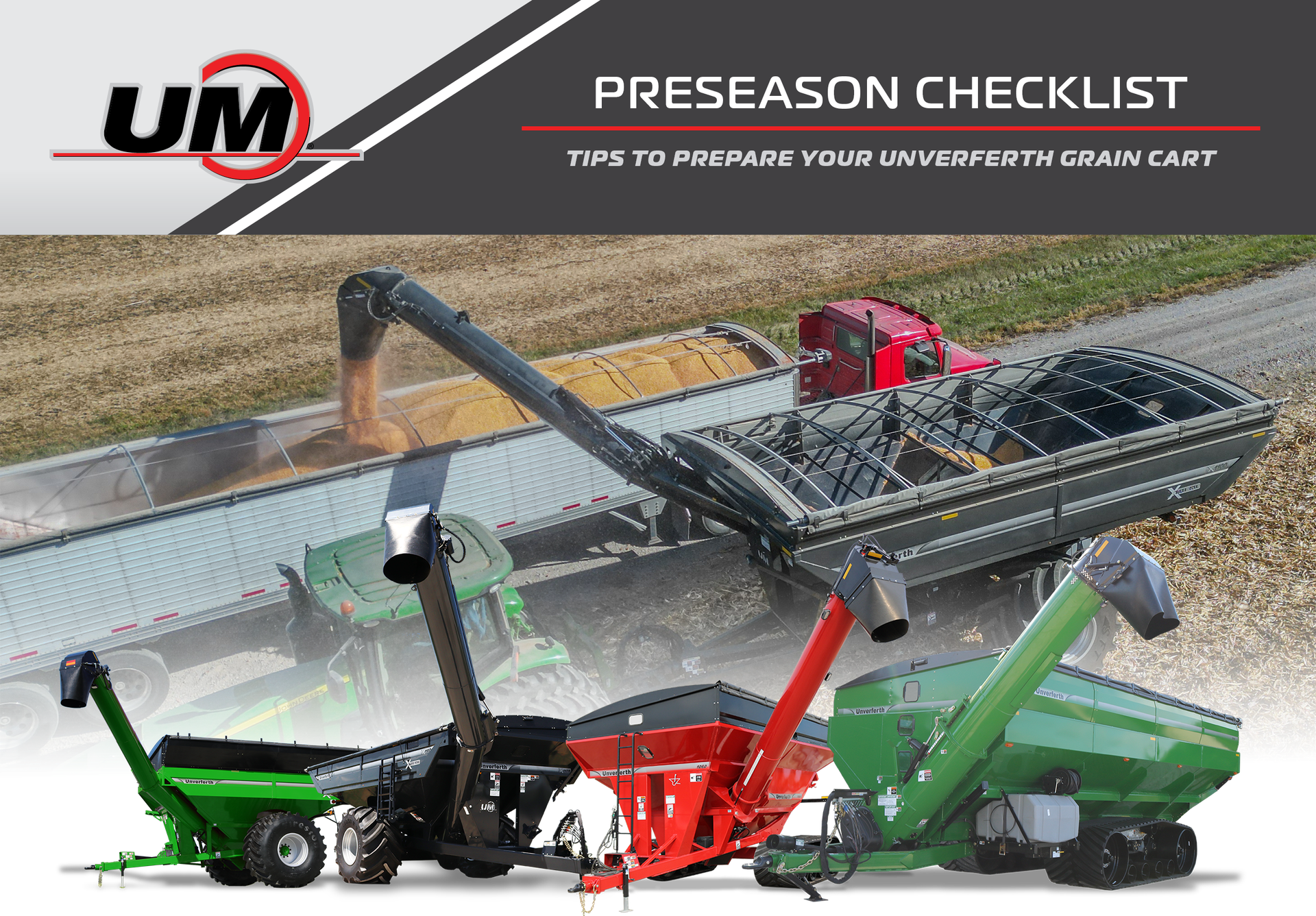
The right preparation ensures that your equipment runs smoothly. Use this checklist to help prepare your Unverferth Grain Cart for the upcoming season.
Essential information about preseason prep for Unverferth Grain Carts.
Checks Before Initial Field Use:
Lubricate all grease fittings.
Change auger gearbox oil yearly using 80W-90. Check the oil level with the vertical auger tilted all the way down.
Ensure track auto-greaser is functioning properly if equipped.
Verify tracks are in alignment.
Verify torque on wheel bolts or track idlers.
Verify tire pressure.
Verify drive belts on double auger carts are properly tensioned and in good condition. The tensioner springs should measure 1 ¾” when belts are tensioned.
Verify transport lights are working properly.
Checks After Initial Field Use:
Verify track alignment.
Verify tire pressure.
Verify torque on wheel bolts or track idlers.
SETUP & REFERENCE GUIDE
Unverferth Cart Service Points:
Lubricate all grease fittings.
Ensure that PTO is in good operational condition. Make sure that this telescopes in and out as it should and is greased properly.
Change auger gearbox oil yearly using 80W-90. Check the oil level with the vertical auger tilted all the way down.
Verify drive belts on double auger carts are properly tensioned and in good condition. The springs should measure 1 ¾” when belts are tensioned.
Verify transport lights are working properly.
Flighting - Check flighting to make sure that this is not worn past an acceptable amount and is in good condition.
Safety Components - Ensure safety chains, lights and SMV's are all in good working condition.
Hopper Components - Ensure interior of cart is in good working condition with no loose components inside.
Tarp - Ensure Tarp is free from tears and rolls freely.
If equipped with electric tarp, please refer back to decal for specific instructions.
Undercarriage
Wheels - Ensure that wheels nuts are torqued to the proper spec. On new carts especially it is critical to re-torque wheels to the appropriate spec once a load has been applied to the cart.
Tires - Ensure that tires are in good working condition. Ensure that tires are operating at the proper pressure recommended in owner’s manual.
Brakes - If a cart is equipped with brakes, ensure that brakes are not dragging and in good working condition. Make sure caliper and disk is in good shape. Make sure the tractor pulling this cart is equipped with the proper brake hook-up. Failure to connect brakes when operating may cause heat build-up and brakes to drag even though they are not connected due to oil expansion in lines.
Wheel Nuts
Tracks:
Ensure track belt is in good working condition and free from rips and tears.
Ensure that belt is running true and is aligned properly. We do not want any heat building up from improper alignment. After running the cart for ½ mile to mile in straight course, check guide lugs for heat build-up on both sides. If heat is present make adjustments. Refer to manual for proper steps.
Check belt tension. Current tracks are equipped with hydraulic tension. Ensure that hydraulic pressure is within 100 PSI of recommended pressure.
Bearing and Idler Condition. Ensure wheel nuts and lugs are torqued properly. Check bearings for end play. This can be done by jacking up the track and taking the tension off.
Lubrication - Ensure that autogreaser is set at the proper interval and full of grease. If cart is not equipped with autogreaser, ensure that grease bank lines are full and in good working condition. Grease hubs on wheels. All grease locations have purgeable seals.
Autogreaser
Scale Components:
Ensure proper calibration number is stored in scale device.
Ensure that all wires are routed properly and connected securely to junction block and load cells.
For Recalibration refer to the equation below. We need to make sure we are using full cart loads. In addition to this, it is recommended to use the sum of several cart loads as this will increase our accuracy with a larger sample size.
Operation Checks:
Ensure auger folds out and locks properly.
Condition the tracks if they are still tacky/green rubber.
Ensure PTO is operated at 1000 rpm actual speed (operating too slow can cause severe driveline damage).
Verify the tarp is open before unloading.
Ensure the joystick is connected to the same battery source as the 7-pin plug on the cart (if equipped).
Ensure all valves on the joystick hydraulic block are locked in the neutral position (if equipped).
Tractor Hookup:
Ensure drawbar position is 20 inches from the PTO.
Verify the proper category hitch and pin are being used for your specific grain cart.
Install plastic wear shoe underneath the grain cart hitch to reduce wear.
Hook up safety chain.
Hook up SCV hoses in the desired order.
Set all hydraulic flows to 4-5 GPM on standard units.
Set hydraulic flow to 4-6 GPM for units equipped with a joystick.
If equipped with a water delivery system, set the hydraulic flow for the pump to a minimum and then increase the hydraulic flow until the water pressure reaches 40-60 PSI.
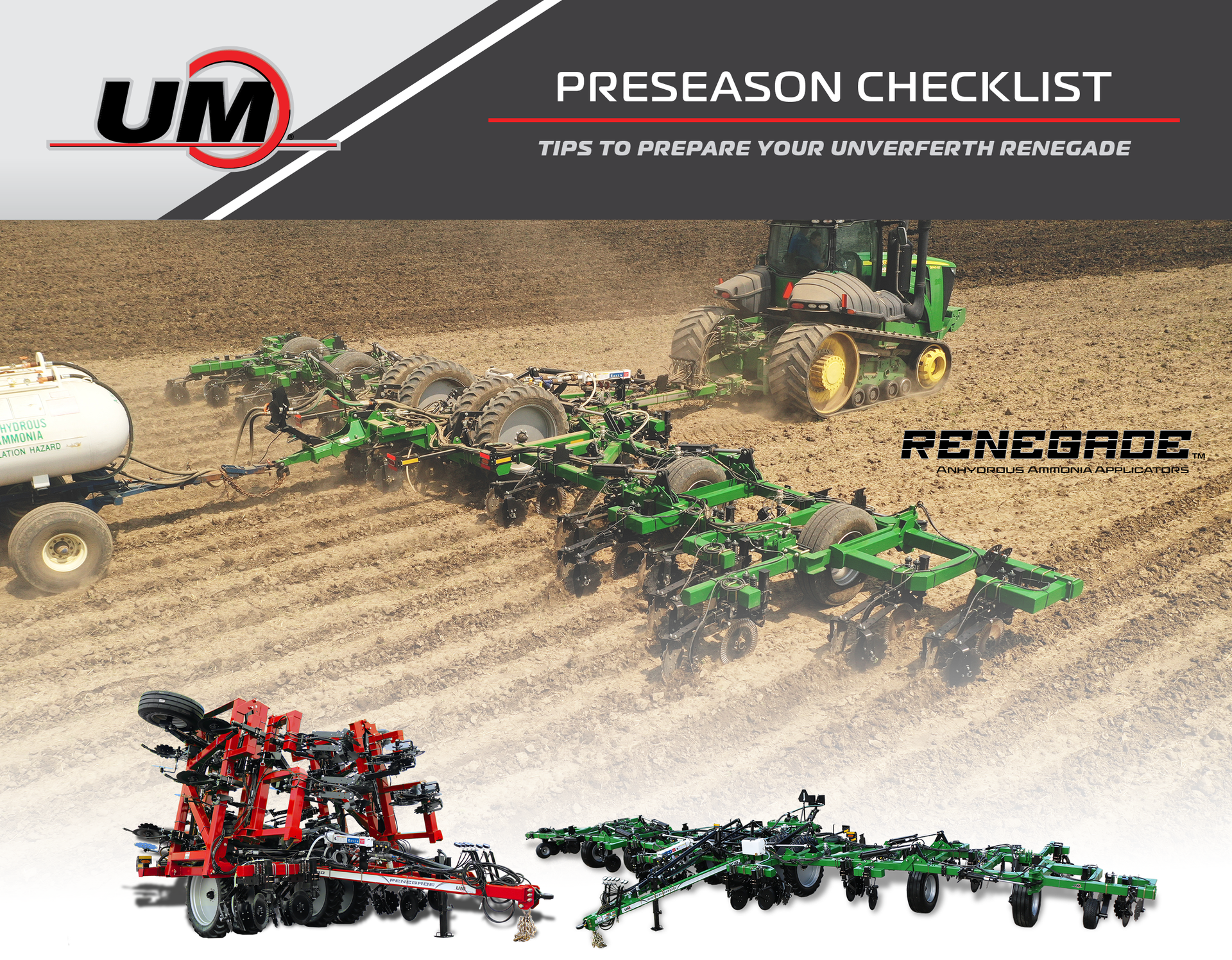
The right preparation ensures that your equipment runs smoothly. Use this checklist to help prepare your Unverferth Renegade Anhydrous Applicator for the upcoming season.
Essential information about preseason prep for Unverferth Renegade Anhydrous Ammonia Applicator tool.
Checks Before Initial Field Use:
Verify no hydraulic leaks
Verify torque on the wheel bolts
Verify tire pressure
Verify all anhydrous hoses are clamped on the knives tightly
Verify all threaded connections on the bar are tight
Verify weather conditions are favorable for application
Verify tool bar is level when in the ground
Check seal quality on the tank hook-up hose
Fill onboard water tank
Have proper PPE available
Checks After Initial Field Use:
Make sure that the bar is properly blead off.
See bleed off procedure on the back
Verify torque on the wheel bolts
Verify tire pressure.
SETUP & REFERENCE GUIDE
Tractor Connections
Tractor Hydraulic Remotes:
Main raise and lower
Main Wing fold/ Secondary wing Fold
Third wing fold (if applicable)
HP+ Boost Pump (only for N-Serve option)
Tractor Electrical Connection:
ISO bus plug
Foot switch
Lights
Setup
Thorough instructions are available in your manual.
Cooler Setup:
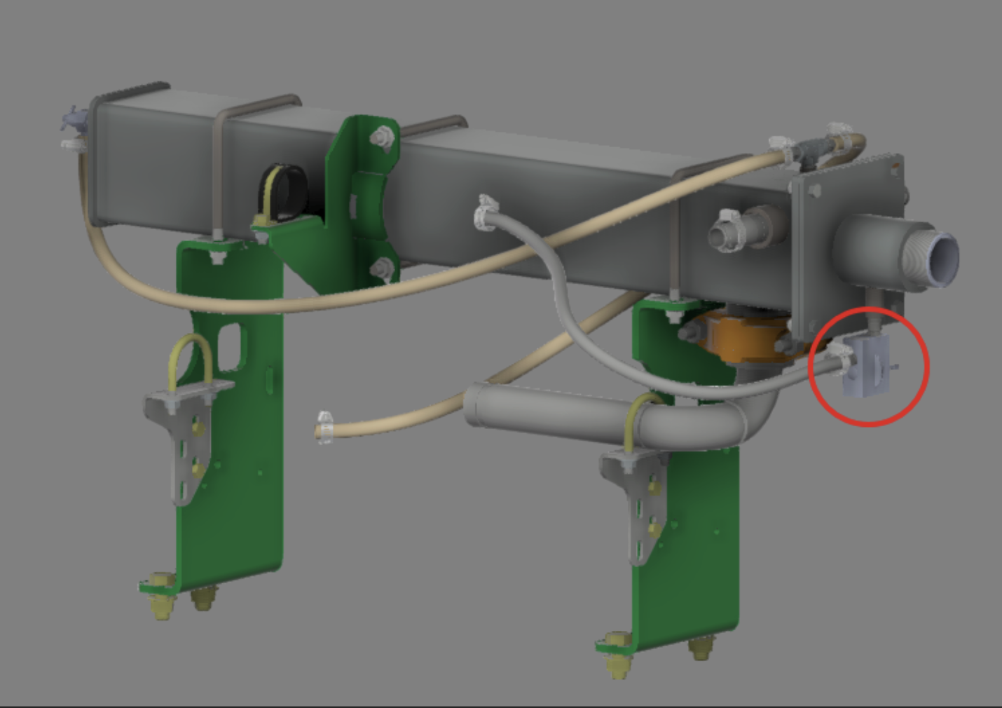
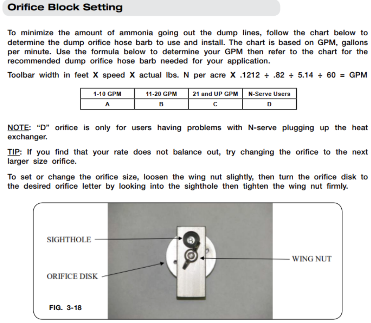
Verify orifice setting is correct for the known application rate
Knife Depth Setup:
Toolbar must be set in the ground when leveling.
3500, 2500 start by setting the center section depth with the adjustable tie-rod near the transport switch.
1500-depth stop collars
When desired depth is set on the center section, the secondary wing fold on the applicator by all-thread adjustable bar
When the secondary wing is set level the third wing fold set gauge wheel with all-thread adjustable bar (when necessary pin adjust gauge wheel.)
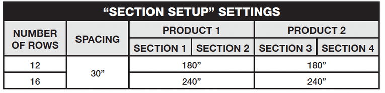
Section Setup for Rate Controller:
Full Rate Controller setup is in the provided manual
Pressure sensor setup
Pressure sensor 1 (0-250PSI)
Pressure Sensor 2 (0-250PSI)
NH3 boost pump setup
Pressure sensor 4 (Delta Press-NH3)
Engage hydraulic to 8-15 gallons per minute
Meter Cal number
Tag on the flow meter should indicate Cal number (Lbs of N)
Toolbar Bleed-Off Procedure:
Toggle the Master Switch to OFF position
Completely close the main shut-off valve on the tank
Resume field application until the pressure gauge reads no remaining pressure. NEVER ASSUME THE SYSTEM IS COMPLETELY EMPTY AT THIS TIME!
Verify the Master Switch and all Section Switches are in the OFF position
Open the emergency shut-off valve (valve with manual handle)
Bleed and disconnect the tank supply hose
Bleeder valve on tank hose
While standing upwind from the implement slowly open the primary bleed valve until it is fully open. Ammonia will discharge out of the vapor knives on the toolbar.
Always bleed system slowly when time permits by leaving them open over a period of time
Remain at the primary bleed valve until ammonia cloud is no longer coming out of vapor knives. Check pressure and temperature gauges to verify the pressure reads zero and no frost on the parts
Open secondary bleed valve to relieve any remaining liquid ammonia
Re-verify the pressure gauge reads zero and all components are NOT cold to the touch before opening the system
End-of-Season Checks:
Clean out screens located on ball valve assembly.
Take cooler off and coat inside with kerosene or fuel oil (recommended)
Necessary when running N-serve due to the high corrosive nature of the product
Tips to Prepare Your Unverferth Raptor Strip-Till for Use
Updated: August 2026
The right preparation ensures that your equipment runs smoothly. Use this checklist to help prepare your Unverferth Raptor Strip-Tillage Tool for the upcoming season.
Essential information about preseason prep for Unverferth Raptor Strip-Tillage Tools.
Checks Before Initial Field Use:
Replace meter and agitator bearings annually
Replace orifice nozzles if there are signs of deterioration or breakage
A two position meter door adjustment kit is available for some applications where low rates and/or lower density products may require. Part #48450 is available to order through your dealer at a list price of $330 and can be installed in 2 hours.
Grease all coulter hubs. The coulter hubs feature triple-lip seals. Do not over grease or seal damage will occur.
Verify torque on the wheel bolts.
Verify tire pressure.
Verify proper blockage monitor operation. Use Function F1 to check if all sensors are present after several minutes of use.
Calibrate each product scale per the instructions in the manual. Product calibration is DT only. Page 3-14 in Manual 47979-0.
Run a dry air test/check for air leaks at the tank lids and meter doors.
Open tank lids & inspect rubber seals for damage/wear. Remove meter doors and inspect rubber seals for damage/wear.
Run the fan. Feel around the edges of the tank lids to find any excessive air leaks. Feel around edges of meter doors for the same.
Checks After Initial Field Use:
Verify torque of the wheel bolts.
Verify tire pressure.
Check system for air leaks (DT Models only - see above)
Verify the proper fertilizer rate is applied. If not acceptable, follow the catch test calibration procedure in the manual. (DT Models only - see above).
SETUP & REFERENCE GUIDE
Hydraulic Settings
Gallons Per Minute:
Main Lift Up/Down – Recommend 20 GPM
Toolbar Fold – Recommend 10 GPM
Fertilizer Meters – Requires at least 15 GPM
Fan – Requires at least 20 GPM
Tractor Remote hookup:
Main Lift Up/Down
Toolbar Fold
Hydraulic Jack/Fertilizer Meters
Fan
Case Drain for Low Pressure Return
Gear Ratio and Fan Setup (DT Models Only)
Gear Ration:
Standard 2.0:1 gear ratio will accommodate a rate of 35-275 lbs/acre per bin up to 6 mph.
Optional 1.6:1 gear ratio will accommodate 300+ lbs/acre per bin
Blockage Monitor Setup:
Refer to the Visum blockage monitor manual for set-up procedure
The different function numbers correspond to:
F1: List Sensors
F2: Beep Volume
F3: Brightness
F4: Check Address
F5: Add Sensors
F6: Show Monitor ID
Fan Setup (DT Models Only):
Ensure the case drain hose is connected to the tractor
Start with SCV at lowest flow setting
Increase flow until 30 inches of water or max flow is reached on the pressure gauge
Always shut off fan by placing tractor SCV into float position
Narrow Tall Berm:
Position row cleaners close to the coulter blade. (Ensure no rotational interference between row cleaners and coulter hub) (2015/2030 only)
Adjust closing coulters to maximum angle.
Move coulter arms to the narrow setting.
Increase coulter arm spring pressure. (Gen 2 and GEN 1A)
Remove all firming wheel pressure.
Wide Flat Berm:
Position row cleaners away from the coulter blade. (2015/2030 only)
Adjust closing coulters to minimum angle.
Move coulter arms to the wide setting.
Decrease coulter arm spring pressure.
Increase firming wheel pressure.
Depth Setting:
Shank depth can be adjusted in 1” increments. This is done by removing the depth pin and sliding the shank to desired depth. Each shank has an accompanying depth indicator.
Adjust wing gauge wheel depth so that the toolbar runs level.
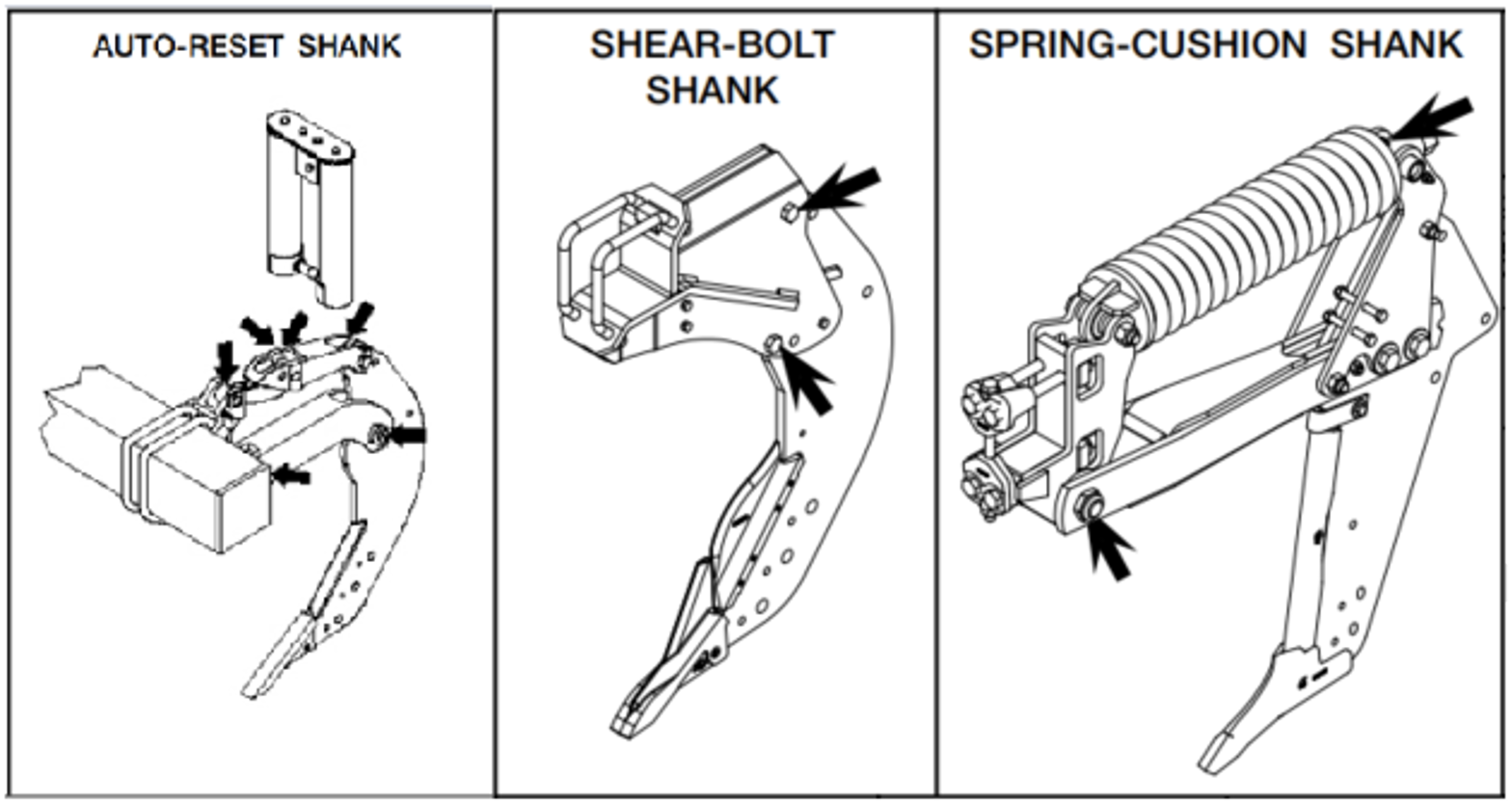
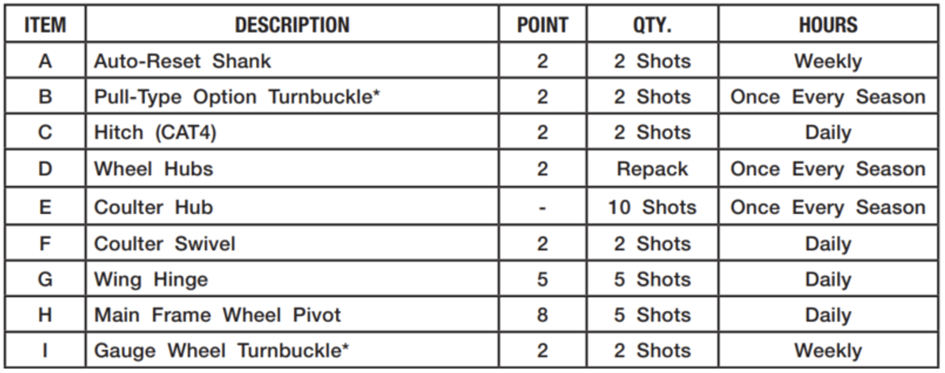
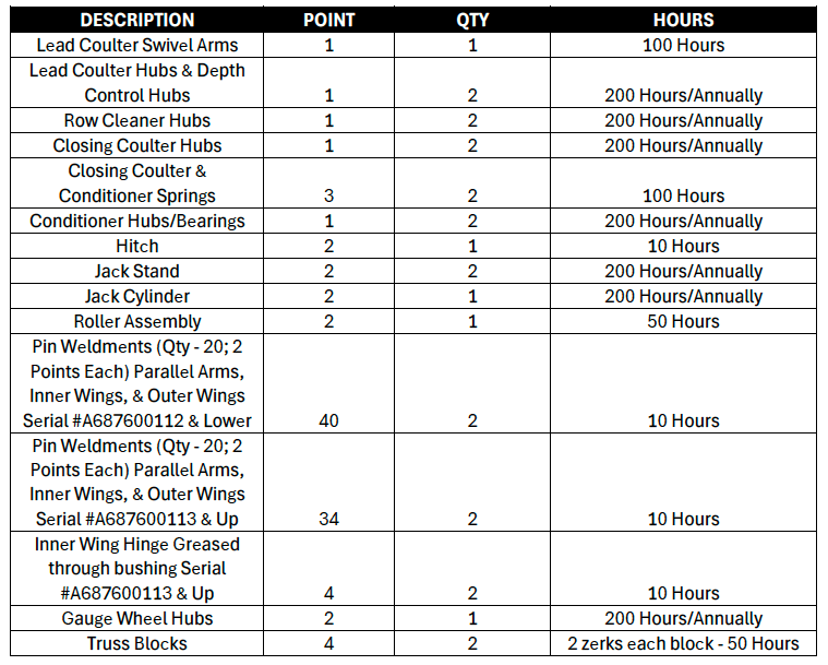
Lubrication Points
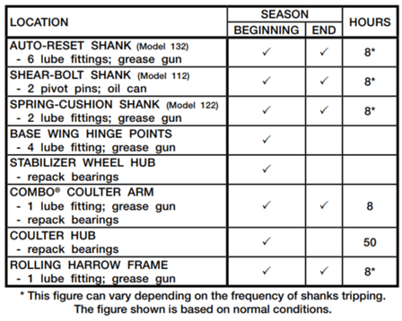
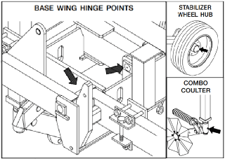
To keep your implement in top operating condition and to assure its proper performance and reliability for a long period of time, periodic inspection and lubrication is a must.
Tips to Prepare Your Orthman 1tRIPr & TRU-aPLYr Strip-Till for Use
Updated: August 2026
The right preparation ensures that your equipment runs smoothly. Use this checklist to help prepare your Orthman 1tRIPr strip-tillage tool & TRU-aPLYr for the upcoming season.
Essential information about preseason prep for Orthman 1tRIPr Strip-Tillage Tool.
Checks Before Initial Field Use:
Ensure that the parallel arm, row unit pivot point, and basket bushings are not worn.
Ensure that all bearings (depth banded coulter, row cleaner, wavy coulters, and basket) are free.
Ensure that the coulter inside the depth bands is of sufficient diameter to cut the residue. Typically, when you have 1 ½” of coulter showing outside of the depth bands, it’s time to replace.
Examine the mole point. If it is severely rounded on the leading edge, replace.
On the liquid shank, make sure that there is adequate hard surfacing protecting the side of the shank and liquid tubes. If not, add new hard surfacing. If the hard surfacing is completely worn off, install new shanks.
On the dry shank, verify that the side protection plates are not worn. If worn, replace.
Verify that the fertilizer tubes are in good condition and not damaged.
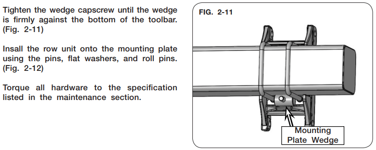
Check the condition of the U-bolts and wedge that mount the row unit to the toolbar. Make sure that the hardware is tight, and the row units are square.
Check the condition of the down pressure and reset springs. Make sure none are damaged, and they are adjusted the same.
On the 1tRIPr I, grease the parallel arm bushings and the basket bushings daily to ensure longevity.
On the 1tRIPr II, grease the fold linkage every 50 hours. On the XD, grease the lift linkages every 50 hours.
Checks After Initial Field Use:
Ensure that the parallel arm, row unit pivot point, and basket bushings are not worn.
Ensure that all bearings (depth banded coulter, row cleaner, wavy coulters, and basket) are free.
Ensure that the coulter inside the depth bands is of sufficient diameter to cut the residue. Typically, when you have 1 ½” of coulter showing outside of the depth bands, it’s time to replace.
Examine the mole point. If it is severely rounded on the leading edge, replace.
On the liquid shank, make sure that there is adequate hard surfacing protecting the side of the shank and liquid tubes. If not, add new hard surfacing. If the hard surfacing is completely worn off, install new shanks.
On the dry shank, verify that the side protection plates are not worn. If worn, replace.
Verify that the fertilizer tubes are in good condition and not damaged.
Check the condition of the U-bolts and wedge that mount the row unit to the toolbar. Make sure that the hardware is tight, and the row units are square.
Check the condition of the down pressure and reset springs. Make sure none are damaged, and they are adjusted the same.
On the 1tRIPr I, grease the parallel arm bushings and the basket bushings daily to ensure longevity.
On the 1tRIPr II, grease the fold linkage every 50 hours. On the XD, grease the lift linkages every 50 hours.
TRU-aPLYr CHECKLIST
Essential information about preseason prep for Orthman TRU-aPLYr.
Checks Before Initial Field Use:
Verify all fertilizer meter and hoses are clear of old fertilizer.
Run a dry air test to verify that all fertilizer hoses are clear of any blockages and moisture and have no holes or kinks.
Verify proper blockage monitor operation.
Calibrate bin scales if necessary.
Verify all the shields are in place ( See operators manual)
Perform catch test calibration after filling with fertilizer.
Check wheel torque and tire pressure on XD toolbar or TRU-STEER cart.
Checks After Initial Field Use:
Verify the applied fertilizer rate is within an acceptable range of the target rate. If the rate is not acceptable, repeat catch test calibration or perform a calibration with the scale.
Continue to monitor for developing fertilizer and air leaks.
Double check tire wheel bolt torque and tire pressure.
Check TRU-STEER Tire alignment to ensure it is centered between the strips.
SETUP & REFERENCE GUIDE
Tractor Requirements:
Cat 3/3N or Cat 4/4N quick hitch required depending on implement size.
Cat 4 or Cat 5 drawbar depending on implement size.
22GPM @ 2650psi hydraulic requirement if equipped with TRU-aPLYr.
12VDC 60A power requirement if equipped with TRU-aPLYr.
Case drain connection requirement if equipped with TRU-aPLYr.
Connections:
One Hydraulic SCV for a folding unit
One Hydraulic SCV for the fan if equipped with TRU-aPLYr.
Case drain connection if equipped with TRU-aPLYr.
ISOBUS connection required if equipped with TRU-aPLYr.
12VDC 60A battery connection if equipped with TRU-aPLYr.
Tips to Prepare Your Blu-Jet 20-Series Anhydrous Ammonia Applicator for Use
Updated: August 2026
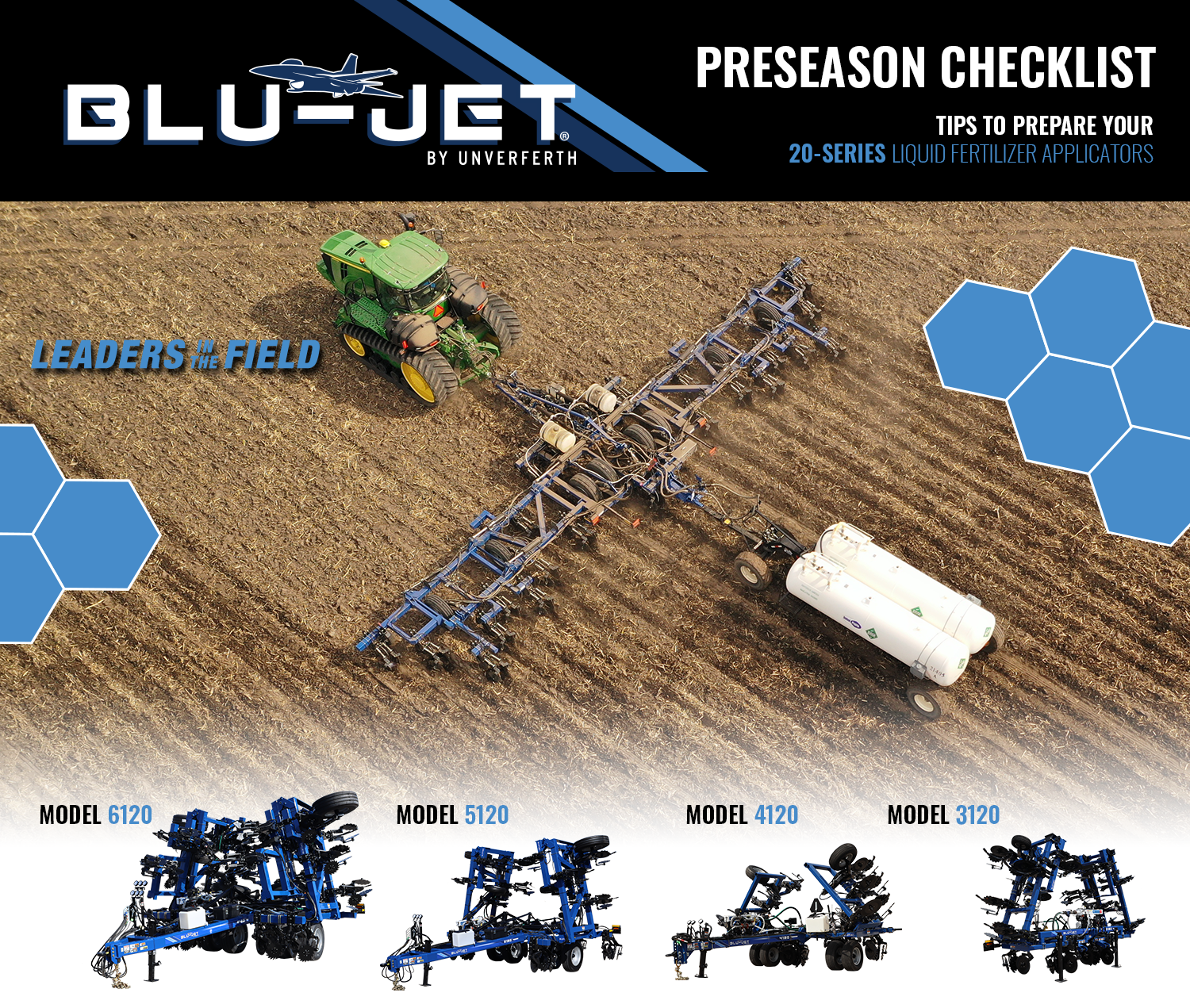
The right preparation ensures that your equipment runs smoothly. Use this checklist to help prepare your Blu-Jet 20-Series Anhydrous Applicator for the upcoming season.
Essential information about preseason prep for Blu-Jet 20-Series Anhydrous Ammonia Applicator tool.
Checks Before Initial Field Use:
Verify no hydraulic leaks
Verify torque on the wheel bolts
Verify tire pressure
Verify all anhydrous hoses are clamped on the knives tightly
Verify all threaded connections on the bar are tight
Verify weather conditions are favorable for application
Verify tool bar is level when in the ground
Check seal quality on the tank hook-up hose
Fill onboard water tank
Have proper PPE available
Checks After Initial Field Use:
Make sure that the bar is properly blead off.
See bleed off procedure on the back
Verify torque on the wheel bolts
Verify tire pressure.
SETUP & REFERENCE GUIDE
Tractor Connections
Tractor Hydraulic Remotes:
Main raise and lower
Main Wing fold/ Secondary wing Fold
Third wing fold (if applicable)
HP+ Boost Pump (only for N-Serve option)
Tractor Electrical Connection:
ISO bus plug
Foot switch
Lights
Ag Leader ISO Switchbox cable (if applicable)
Setup
Thorough instructions are available in your manual.
Cooler Setup:
Verify orifice setting is correct for the known application rate
Knife Depth Setup:
Toolbar must be set in the ground when leveling.
6120, 5120 start by setting the center section depth with the adjustable tie-rod near the transport switch.
4120-depth stop collars
When desired depth is set on the center section, the secondary wing fold on the applicator by all-thread adjustable bar
When the secondary wing is set level the third wing fold set gauge wheel with all-thread adjustable bar (when necessary pin adjust gauge wheel.)
Section Setup for Rate Controller:
Full Rate Controller setup is in the provided manual
Pressure sensor setup
Pressure sensor
Min pressure: 0 psi
Max pressure: 250 psi
Min V/A: 1.0 V
Max V/A: 5.0 V
NH3 boost pump setup
Engage hydraulic to 8-15 gallons per minute
Meter Cal number
Tag on the flow meter should indicate Cal number (Lbs of N)
Divide by 10 as Raven sensor are noted as pulses per 10 gallon.
AG Leader ISO Switchbox setup (if applicable)
Map all the switches on the tractor ISO Aux setup screen
Turn on ISO Aux on the tractor setup screen
Verify all the switches are working properly
Toolbar Bleed-Off Procedure:
Toggle the Master Switch to OFF position
Completely close the main shut-off valve on the tank
Resume field application until the pressure gauge reads no remaining pressure. NEVER ASSUME THE SYSTEM IS COMPLETELY EMPTY AT THIS TIME!
Verify the Master Switch and all Section Switches are in the OFF position
Open the emergency shut-off valve (valve with manual handle)
Bleed and disconnect the tank supply hose
Bleeder valve on tank hose
While standing upwind from the implement slowly open the primary bleed valve until it is fully open. Ammonia will discharge out of the vapor knives on the toolbar.
Always bleed system slowly when time permits by leaving them open over a period of time
Remain at the primary bleed valve until ammonia cloud is no longer coming out of vapor knives. Check pressure and temperature gauges to verify the pressure reads zero and no frost on the parts
Open secondary bleed valve to relieve any remaining liquid ammonia
Re-verify the pressure gauge reads zero and all components are NOT cold to the touch before opening the system
End-of-Season Checks:
Clean out screens located on ball valve assembly.
Take cooler off and coat inside with kerosene or fuel oil (recommended)
Necessary when running N-serve due to the high corrosive nature of the product
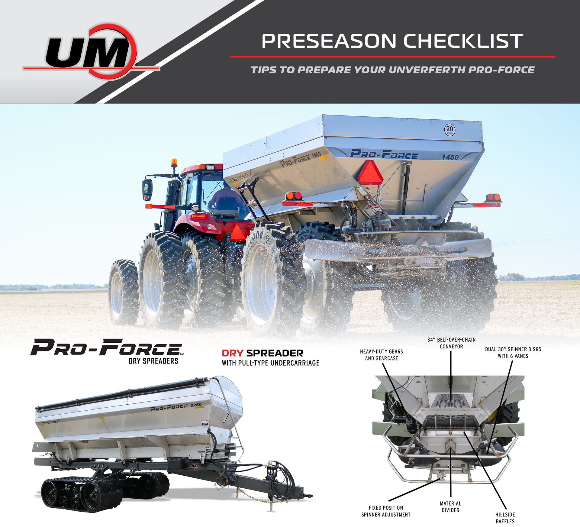
Essential information about preseason prep for Unverferth Pro-Force Fertilizer Applicator.
Checks Before Initial Field Use:
Check your equipment and confirm that there are no hydraulic leaks.
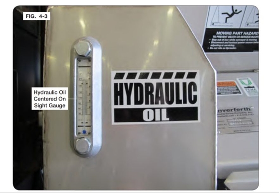
If equipped with a hydraulic oil reservoir, check reservoir level (see hydraulic reservoir image)
Ensure supply valve is open from reservoir to pump
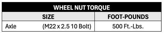
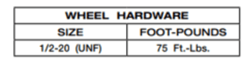
Verify torque on the wheel bolts (see wheel nut torque table)
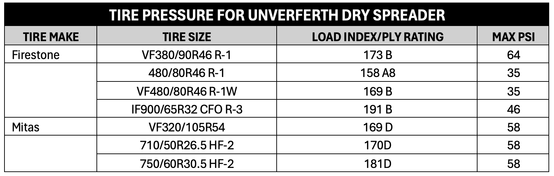
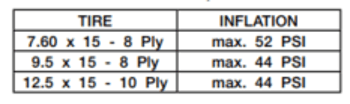
Check the tire pressure on your equipment (see the pressure table)
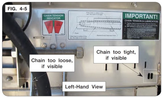
Verify that the conveyor is properly tensioned on both sides (see chain tension image)
If equipped with tracks, verify proper belt tension and proper lubrication are up to date.
Follow lubrication chart recommendations (see lubrication chart image)
Verify spinner vanes are in good shape, and not worn or bent
If equipped with Air Command, make sure fan inlet screen is free of debris and fan rotates freely.
If equipped, drop Air Command manifold lower inspection plate and make sure valves are free of debris.
Ensure proper operation of the conveyor(s) and spinners
Spray the conveyor chain on both side with a 50/50 mix of used motor oil and diesel fuel to reduce corrosion and wear. Re-apply at the end of the application season.
Checks After Initial Field Use:
Verify the conveyor is properly tensioned on both sides. Check tension daily (see chain tension image)
Verify torque on the wheel bolts. Check periodically until the wheel bolts remain tight (see wheel nut toque chart)
Verify tire pressure (see tire pressure chart)
SETUP & REFERENCE GUIDE
Hydraulic Flow Requirement:
Combined Hydraulic System: Supply hoses 1 & 2 require a combined flow of 38 gpm. A unit equipped with Air Command TM Section Control requires an additional 14 gpm of flow.
Split Hydraulic System: Supply Hoses 1, 2, 3, & 4 require a combined flow of 60-76 gpm.
PTO Drive Hydraulic System: Requires PTO operation at 1000 rpm. A unit equipped with Air Command Section Control also requires 14 gpm of flow from the tractor remote.
Tractor Hydraulic Connections:
Combined Hydraulic System
Supply hose 1 to remote 1 (blue hose wrap or + tan hose grip)
Supply hose 2 to remote 2 (blue hose wrap or + tan hose grip)
Return hose 1 to low-pressure return or remote 1 (unmarked or - tan hose grip)
Return hose 2 to low-pressure return or remote 2 (unmarked or - tan hose grip)
Case Drain (-yellow hose wrap or grip)
Air Command supply to remote 3 (+ yellow hose grip, if equipped)
Air Command return to remote 3 (- yellow hose grip, if equipped)
Brakes (red hose wrap or grip, if equipped)
Split Hydraulic System
Spinner supply 1 to remote 1 (+ green hose grip)
Spinner supply 2 to remote 2 (+ green hose grip)
Spinner return 1 to remote 1 (- green hose grip)
Spinner return 2 to remote 2 (- green hose grip)
Conveyor supply 1 to remote 3 (+ orange hose grip)
Conveyor supply 2 to remote 4 (+ orange hose grip)
Conveyor return 1 to remote 3 (- orange hose grip)
Conveyor return 2 to remote 4 (- orange hose grip)
Case drain (- yellow hose grip)
PTO Drive Hydraulic System
1 3/4"-20 spline PTO Shaft
Air Command supply to remote 1 (+ yellow hose grip, if equipped)
Air Command return to remote 1 (- yellow hose grip, if equipped)
Air Command Case drain (- yellow hose grip, if equipped)
Brakes (red hose grip, if equipped)
Tractor Electrical Connections:
Scale Head (if equipped)
Lights
ISO Rate Controller (if equipped)
Foot Switch
Electric Tarp/Oil Cooler (if equipped)
Gate Height:
Gate height needs will vary by product, application rate, application width and application speed. This height will need to be adjusted if the conveyor speed is outside of an optimal 10-40 rpm. Increasing the gate height will slow the conveyor down and decreasing the gate height will speed it up.
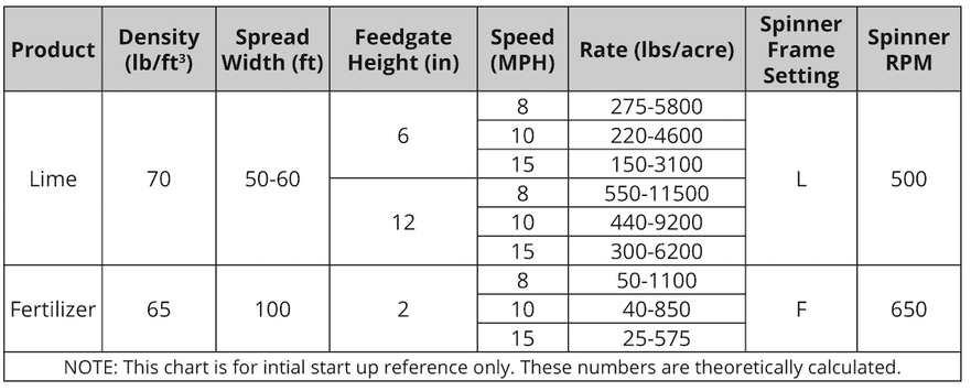
Adjust spreader constant according to gate height setting. To calculate the spreader constant for a single bin spreader, divide 618 by the gate height in inches. For the complete list, please reference the set up guide.
Scale Setup:
Calibrate your scale by loading a known weight of material on the spreader.
Navigate to Settings > System Settings > Scale Set Up > Scale Calibration.
Enter the known weight as "Actual" and copy the current weight into "Previous".
Touch "Calibrate"
Starting Cal number for models 1055-1455 is 32,000
Starting Cal number for models 1655-2655 is 48,000
Catch Test Calibration:
Perform a catch test calibration for each equipped product bin before initial use and if the application rate error is larger than desired. To watch a video of this process in detail visit this link: Pro-Force Dry Spreader Field Setup
Spread Pattern Test:
Verify proper spread width
Verify consistent spread pattern
Verify consistent product mixing when equipped with multiple bins
Recommended adjustments if the spread pattern is not even below
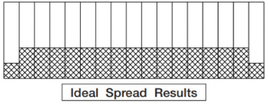
Flat and taper off towards the outside 5 to 10 ft.
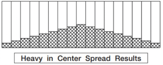
To correct, increase spinner speed and adjust spinner assembly forward
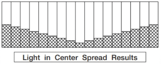
To correct, decrease spinner speed and adjust spinner assembly rearwards
Continued Spread Pattern Test:
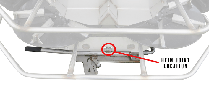
Lengthen the heim joint to move the spinner assembly forward
Shorten the heim joint to move the spinner assembly rearwards
If applying the product with a large gate height, it may be necessary to move the spinner frame back and pin it in one of the four holes marked next to the "L".
Tips to Prepare Your Unverferth Header Transport for Use
Updated: June 2026
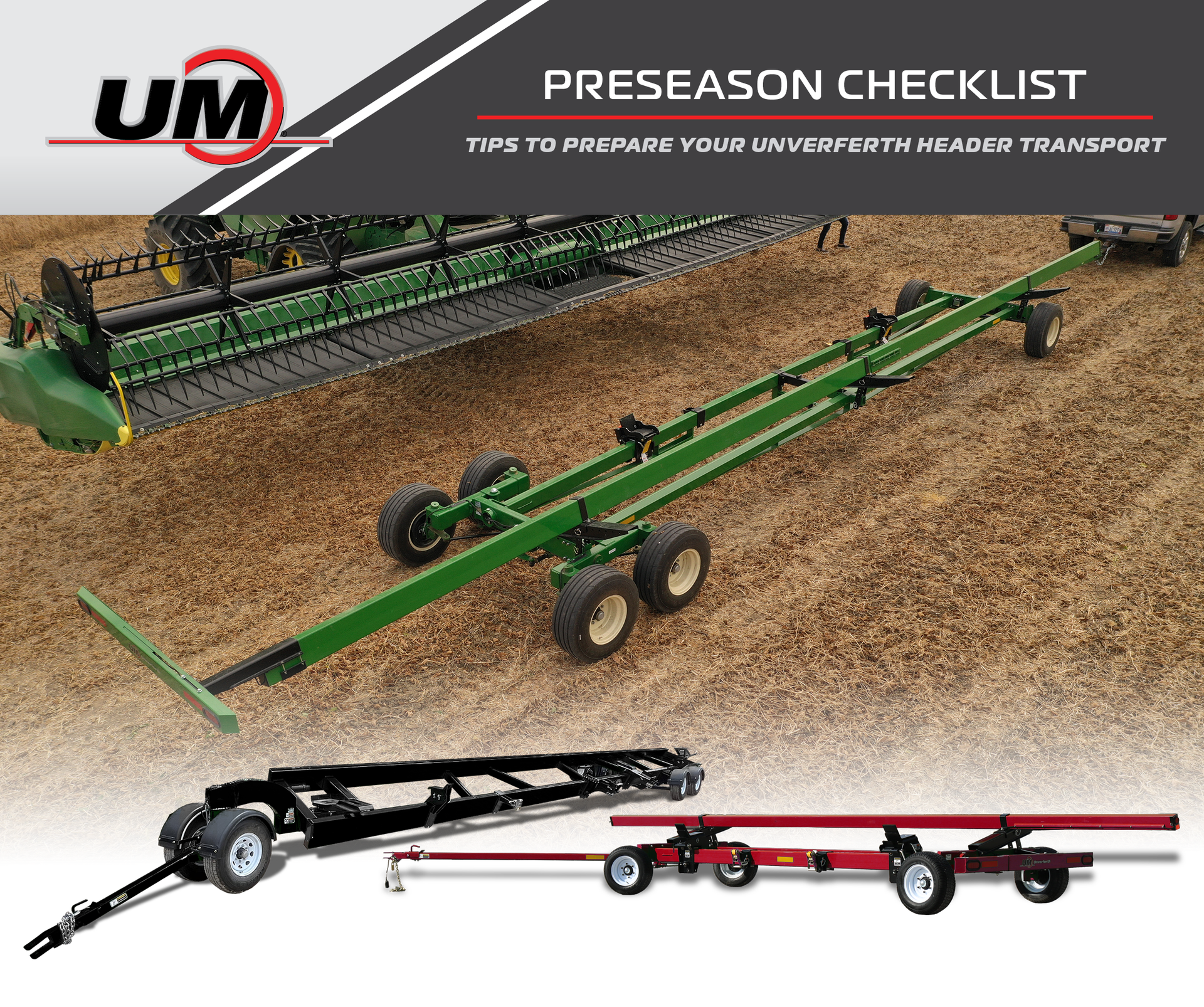
The right preparation ensures that your equipment runs smoothly. Use this checklist to help prepare your Unverferth Header Transport for the upcoming season.
Essential information about preseason prep for Unverferth Header Transports.
Checks Before Initial Field Use:
Lubricate all grease fittings.
Spindles, tongue pivots, swivel tube, tie rod connection pivots. Refer to the manual for all grease locations.
Check tire pressures.
Verify wheel lugs are torqued to spec.
Verify lights are working properly.
Verify that tie-downs and rest brackets are securely mounted.
Inspect brake break-away connections.
Test brake operation.
Inspect Safety Chains.
Verify proper trailing.
Checks After Initial Field Use:
Verify that tie-downs and rest brackets are securely mounted.
Verify wheel lugs are torqued to spec
SETUP & REFERENCE GUIDE
Service Points:
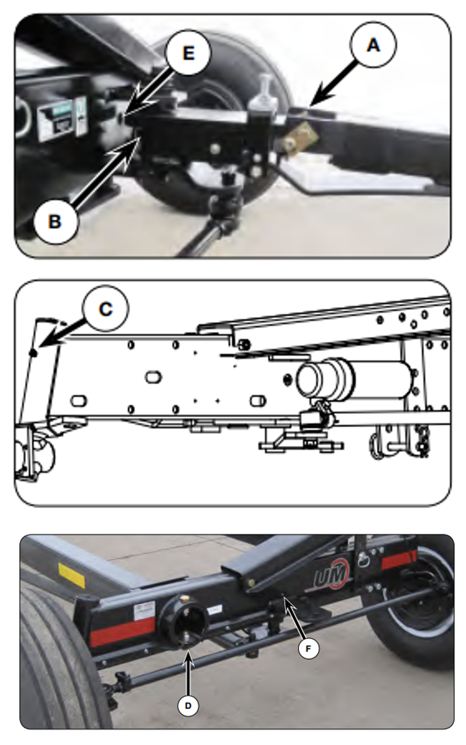
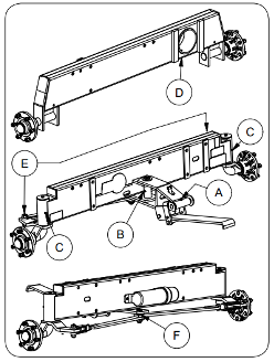
AWS Grease Points (Once per Year)
A. Tongue Hitch Pin (End of Steering Hinge)
B. Steering Hinge Pin (Front of Front Frame) - Rotate tongue to access zerk.
C. Spindle Bearings (Both Ends of Front Axle) - 2 Points
D. Swivel Trunnion (Rear End of Rear Axle)
E. Front Pivot
F. Rear Pivot
HT Grease Points (Once per Year)
A. Tongue Hitch Pin
B. Steering Hinge Pin
C. Spindle Bearings
D. Swivel Trunnion
E. Shoulder Bolts
F. Steering Hinge Rear Pin (Use Anti-Seize)
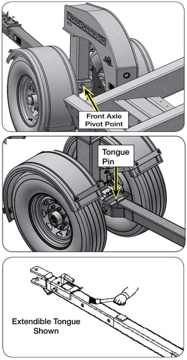
RoadRunner HD Grease Points
A. Tongue Pin (Once Per Year)
B. Tongue Sliding Surface (When Needed)
C. Front Axle Pivot (Every 5 hours)
Check tire pressure.
All-Wheel Steer
11L x 15 – 90 PSI
225/75 x 15 – 65 PSI
320/65 x 15 – 70 PSI
235/85R x 16 – 80 PSI
Header Transport
225/55B12 – 100 PSI
11L-15 F-Range – 90 PSI
RoadRunner HD
225/85R x 16 – 80 PSI
235/75R x 17.5 – 125 PSI
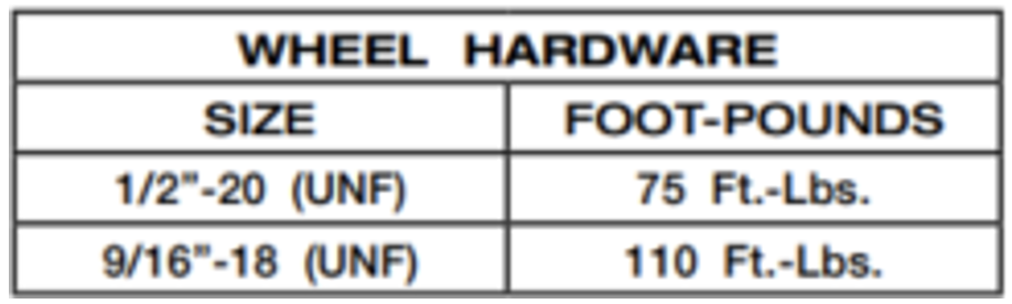
Verify wheel lugs are torqued to spec.
AWS – 75 Ft-Lbs. (1/2”-20 UNF Lugs)
AWS –110 Ft-Lbs. (9/16”-18 UNF Lugs)
HT – 75 Ft-Lbs.
RRHD – 110 Ft-Lbs.
Operation Checks & Fitment Tips
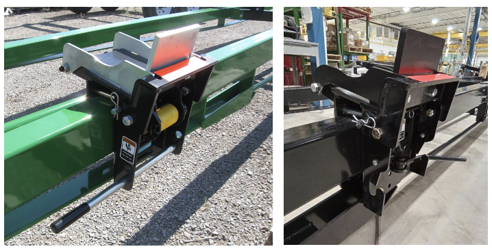
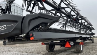
Ensure rest brackets are supporting heads in areas approved by the head manufacturer.
Ensure rest brackets are set to prevent sliding fore and aft.
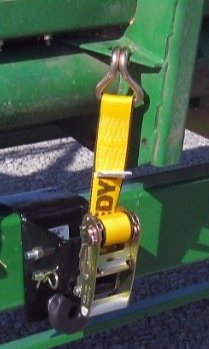
Ensure ratchet strap tie-downs are secure.
Verify proper accessory attachments are used to carry your head if needed.
Verify with your dealer or Unverferth Manufacturing, or refer to this page.
Upper Bar should be adjusted to sit level when loaded.
Upper Bar should typically be adjusted to carry the head directly behind the cutter bar – Verify this position with your head manufacturer or local retailer.
Correct Upper Bar Adjustment
Towing Hookup:
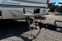
Ensure the clevis, ball joint, or pintle hitch is properly secured and a retaining pin is installed.
Ensure safety chains are properly secured.
Ensure the breakaway controller is attached to the towing vehicle separate from the safety chains.
Inspect trailer plug for corrosion or debris and verify light functionality.
Tips to Prepare Your Unverferth Zone-Builder Subsoiler for Use
Updated: August 2026
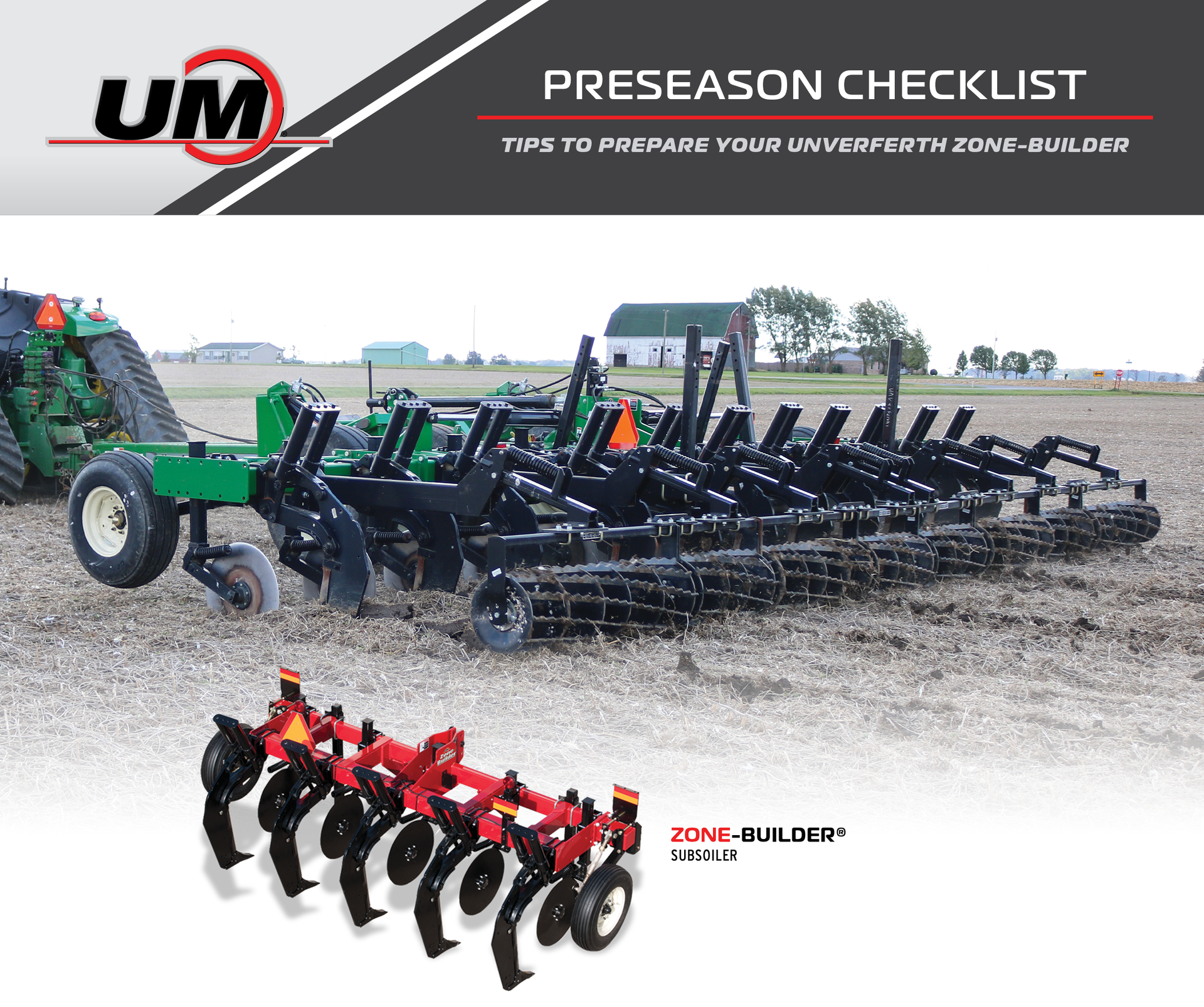
The right preparation ensures that your equipment runs smoothly. Use this checklist to help prepare your Unverferth Zone-Builder for the upcoming season.
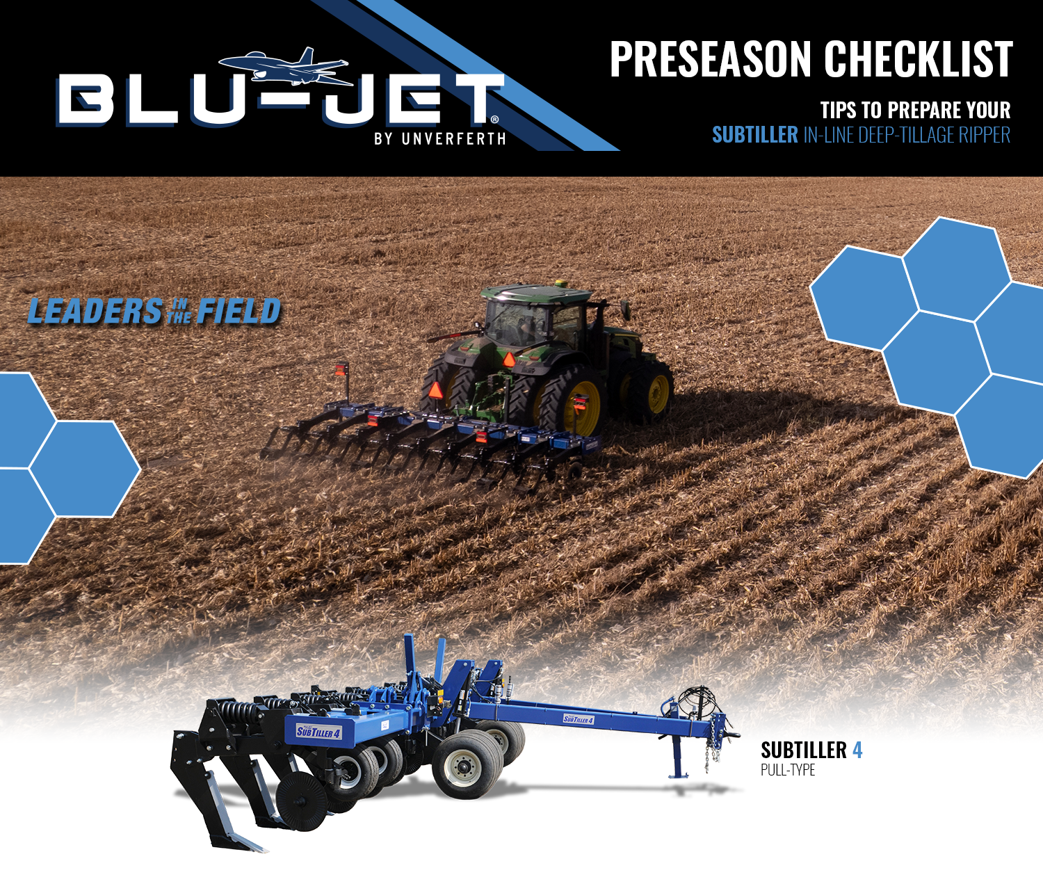
Tips to Prepare Your Blu-Jet SubTiller Tillage Tool for Use
Updated: August 2026
The right preparation ensures that your equipment runs smoothly. Use this checklist to help prepare your Blu-Jet SubTiller Tillage Tool for the upcoming season.
Essential information about preseason prep for Orthman Stalk PULLr.
Checks Before Initial Field Use:
Complete a walk around of the machine
Ensure no bolts or nuts are loose
Inspect row units for any damaged or worn parts
Replace if needed
Inspect V-disks for edge wear and grooving
If excessive edge wear, consider replacement
If grooving, consider changing the orientation
Example: Factory orientation of the V-Disks is left overlaps right. Over the life of the V-Disks a groove will appear in the LH V-Disk and the RH V-Disk will become dull. When this happens, the V-Disk orientation must be changed.
Lubricate all grease points
Unless equipped with gauge wheels or chopper units, the only grease points are on the wing pivot and wing fold linkage.
Please refer to section 4-2 of the manual for the location of grease points on the wheels or choppers.
Checks After Initial Field Use:
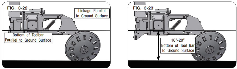
Check to make sure machine bar is running parallel to the ground.
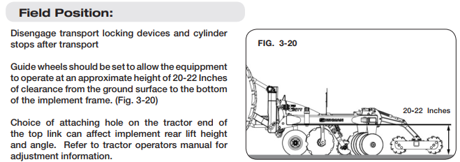
Ensure that the bottom of the bar is roughly 16-20 inches off of the ground.
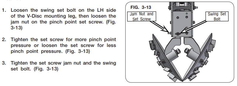
After running several acres, inspect blades in the field to ensure proper pinch point.
If lacking pinch point pressure, the machine will not slice the roots properly
To adjust, loosen the swing set bolt and then loosen the jam nut. Tighten the set screw for more pinch, refer to page 3-9 in the manual for more information.
After running several acres in a new field, pay attention to the row units:
Ensure that they are all riding level
Make sure the row units are not bouncing, if they are, the ground is probably very hard and may need more down pressure to penetrate.
To add or subtract down pressure, loosen the down pressure spring jam nut and adjust the adjustment bolt clockwise to increase pressure.
For more in-field troubleshooting, please reference the manual:
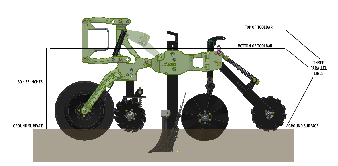
SETUP & REFERENCE GUIDE
Tractor Requirements:
CAT 3/3N or CAT 4/4 quick hitch required depending on implement size
Connections:
Will require one hydraulic SCV if it’s a folding unit